brewer_shipping
Differences
This shows you the differences between two versions of the page.
| Both sides previous revisionPrevious revisionNext revision | Previous revision | ||
| brewer_shipping [2026/05/15 12:31] – andrew | brewer_shipping [2026/05/15 13:34] (current) – andrew | ||
|---|---|---|---|
| Line 21: | Line 21: | ||
| **Installing Brewer on tracker** | **Installing Brewer on tracker** | ||
| + | |||
| Required tools: | Required tools: | ||
| + | |||
| All required tools can be found in the red toolbox found with other Brewer supplies. | All required tools can be found in the red toolbox found with other Brewer supplies. | ||
| - Hex driver – Size 25 | - Hex driver – Size 25 | ||
| Line 28: | Line 30: | ||
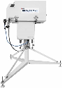
| 1. Bring Brewer to tracker outside. Highly recommended, | 1. Bring Brewer to tracker outside. Highly recommended, | ||
| - | 2. Place the Brewer on the tracker with the rubber feet on the bottom of the instrument lining up with the four-metal mounting tabs and the three bolts protruding from the top of the tracker will line up with holes on the bottom of the instrument. | + | 2. Place the Brewer on the tracker with the rubber feet on the bottom of the instrument lining up with the four-metal mounting tabs and the three bolts protruding from the top of the tracker will line up with holes on the bottom of the instrument. |
| + | |||
| + | {{ : | ||
| a. When placing the Brewer on the tracker the back of the instrument (side opposite the widow) is on the same side of the tracker that has the Plexiglas removable window. If there is no window on the tracker, line up the power button on the instrument with the power button on the tracker. | a. When placing the Brewer on the tracker the back of the instrument (side opposite the widow) is on the same side of the tracker that has the Plexiglas removable window. If there is no window on the tracker, line up the power button on the instrument with the power button on the tracker. | ||
| Line 36: | Line 41: | ||
| 3. Secure the instrument to the tracker by taking the four screws and by hand threading them into the rubber feet of the Brewer. We highly recommend starting each of the four screws by hand to avoid cross threading and not tightening them down fully until each screw is started. This allows for easier installation of the mounting screws. Once all screws are started, use 25 Hex driver to secure the mounting screws. | 3. Secure the instrument to the tracker by taking the four screws and by hand threading them into the rubber feet of the Brewer. We highly recommend starting each of the four screws by hand to avoid cross threading and not tightening them down fully until each screw is started. This allows for easier installation of the mounting screws. Once all screws are started, use 25 Hex driver to secure the mounting screws. | ||
| - | + | {{ : | |
| 4. Once the screws are installed connect the three cables coming from the tracker to the Brewer. Look at the end of the connectors and the receptacles on the Brewer as the cables can only be attached one way. Once the proper match is found screw in the connectors to the Brewer until tight. | 4. Once the screws are installed connect the three cables coming from the tracker to the Brewer. Look at the end of the connectors and the receptacles on the Brewer as the cables can only be attached one way. Once the proper match is found screw in the connectors to the Brewer until tight. | ||
| + | |||
| + | {{ : | ||
| Note: Outdoor connectors can accumulate oxidation, dirt, and grime. This can cause the screw in portion of the connector to feel tight when the cable isn’t fully connected. We have found the best method to ensure proper connection to be screwing the connector, then pushing the plug further into the receptacle and repeating until the connector can not be pushed any further and the threaded portion is hand tight. | Note: Outdoor connectors can accumulate oxidation, dirt, and grime. This can cause the screw in portion of the connector to feel tight when the cable isn’t fully connected. We have found the best method to ensure proper connection to be screwing the connector, then pushing the plug further into the receptacle and repeating until the connector can not be pushed any further and the threaded portion is hand tight. | ||
| Line 44: | Line 51: | ||
| 5. Connect the connector cap from the brewer to the bulkhead cap from the Brewer to as demonstrated below with the chain wrapping around the outside of the cable. | 5. Connect the connector cap from the brewer to the bulkhead cap from the Brewer to as demonstrated below with the chain wrapping around the outside of the cable. | ||
| - | + | {{ : | |
| 6. Remove the UV Dome Cover from the instrument and power on the tracker and then the instrument. Contact the brewer network to let them know that the instrument has been set up. | 6. Remove the UV Dome Cover from the instrument and power on the tracker and then the instrument. Contact the brewer network to let them know that the instrument has been set up. | ||
| + | |||
| **Brewer Packing** | **Brewer Packing** | ||
| + | |||
| 1. Go to computer of the Brewer that needs to be removed and select the software window running the Brewer. Press the ‘Home’ button on your keyboard to take the instrument out of schedule and once the screen reads that the brewer is not taking any measurements press CTRL + Scroll Lock. | 1. Go to computer of the Brewer that needs to be removed and select the software window running the Brewer. Press the ‘Home’ button on your keyboard to take the instrument out of schedule and once the screen reads that the brewer is not taking any measurements press CTRL + Scroll Lock. | ||
| Line 53: | Line 62: | ||
| 3. Remove the tracker cables. | 3. Remove the tracker cables. | ||
| + | |||
| + | {{ : | ||
| + | |||
| a. The protective caps will be linked together to protect their threads. | a. The protective caps will be linked together to protect their threads. | ||
| b. Turn the outer portion of the connector closest to the Brewer. | b. Turn the outer portion of the connector closest to the Brewer. | ||
| Line 62: | Line 74: | ||
| 5. Install the UV dome protector cap onto the UV dome. | 5. Install the UV dome protector cap onto the UV dome. | ||
| + | |||
| + | {{ : | ||
| 6. Detach the Brewer from the tracker by removing the 4 bolts that thread up into the rubber Brewer feet. The Brewer is heavy and awkward, have someone help you move the Brewer to the area you will use for packing the Brewer. | 6. Detach the Brewer from the tracker by removing the 4 bolts that thread up into the rubber Brewer feet. The Brewer is heavy and awkward, have someone help you move the Brewer to the area you will use for packing the Brewer. | ||
| Line 67: | Line 81: | ||
| 7. Affix the piece of stiff foam marked “Zenith Window” over the zenith prism window with electrical tape. | 7. Affix the piece of stiff foam marked “Zenith Window” over the zenith prism window with electrical tape. | ||
| + | |||
| + | {{ : | ||
| 8. Remove the Brewer cover. Manually rotate the zenith prism down to the lamps by turning the brass combination gear mated to the small motor gear. | 8. Remove the Brewer cover. Manually rotate the zenith prism down to the lamps by turning the brass combination gear mated to the small motor gear. | ||
| - | | + | |
| + | {{ : | ||
| 9. The piece of foam marked “Gear” has a split in it. Slide that piece of foam over the top part of the split-gear (upper most gear) in the zenith drive assembly to prevent the split gear from being damaged by impacting against the Brewer cover during travel. | 9. The piece of foam marked “Gear” has a split in it. Slide that piece of foam over the top part of the split-gear (upper most gear) in the zenith drive assembly to prevent the split gear from being damaged by impacting against the Brewer cover during travel. | ||
| + | |||
| + | {{ : | ||
| 10. Insert the piece of foam labelled “Under Spec. Housing”, between the spectrometer case and case base or the heat sink assembly if it is an older single Brewer. | 10. Insert the piece of foam labelled “Under Spec. Housing”, between the spectrometer case and case base or the heat sink assembly if it is an older single Brewer. | ||
| - | + | ||
| + | {{ : | ||
| 11. Place the piece of foam Marked “Viewing Window” and the bag that contained all the foam over the control panel and filter wheels. | 11. Place the piece of foam Marked “Viewing Window” and the bag that contained all the foam over the control panel and filter wheels. | ||
| + | |||
| + | {{ : | ||
| 12. Use elastics to ensure the container of desiccant inside the instrument cannot open during shipping. Also secure the desiccant tray in place with elastics or cable ties to ensure the tray cannot move around during shipping. | 12. Use elastics to ensure the container of desiccant inside the instrument cannot open during shipping. Also secure the desiccant tray in place with elastics or cable ties to ensure the tray cannot move around during shipping. | ||
| + | |||
| 13. Un buckle the Brewer travel case and remove everything inside other than the 2 straps. Hang the two straps out over the edges of the case to create a +. | 13. Un buckle the Brewer travel case and remove everything inside other than the 2 straps. Hang the two straps out over the edges of the case to create a +. | ||
| + | |||
| 14. Place the brewer in the travel case and place the lose frame over the top of the Brewer. | 14. Place the brewer in the travel case and place the lose frame over the top of the Brewer. | ||
| | | ||
| + | {{ : | ||
| 15. Place one strap around the Brewer length-wise and the other width-wise to secure the Brewer between the frames. | 15. Place one strap around the Brewer length-wise and the other width-wise to secure the Brewer between the frames. | ||
| | | ||
| + | {{ : | ||
| 16. Put the Brewer Travel Case lid back on the instrument and latch it down. Attach the Shipping labels that came with the Brewer case over top of the old labels. | 16. Put the Brewer Travel Case lid back on the instrument and latch it down. Attach the Shipping labels that came with the Brewer case over top of the old labels. | ||
| + | |||
brewer_shipping.1778848283.txt.gz · Last modified: by andrew